Cel shading basics
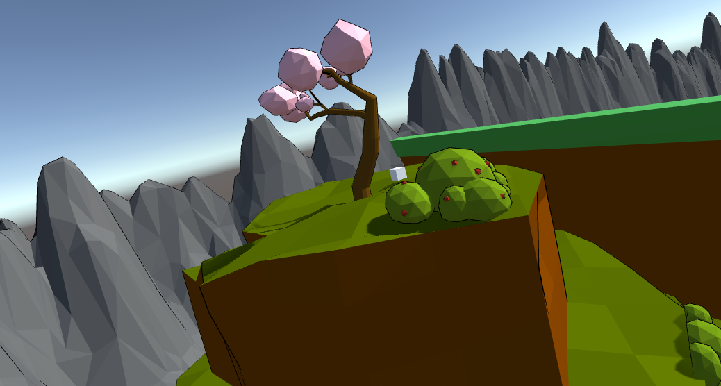
In this article I will go through the shader I wrote for our Ecosystem student project, to implement cel shading. If you are unfamiliar with the concept, this rendering method gives a black outline to everything, giving it a cartoony look.
Before I go any further, you should be aware that I assume baseline familiarity with technical rendering terms and shader basics. If you want to explore shader programming from the complete basics, I highly recommend giving this course a look.
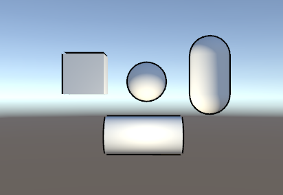
The process is fairly simple, as described here on Wikipedia. In essence, a bloated version of the mesh is rendered first, but only the backfaces, and they are rendered in black (or whatever colour you want the outline to be). Then the ordinary mesh is rendered in front. I have created a small illustration in the following Unity Package:
In order to see the code, you can either go into Assets > Shaders and find it there. Or you can click the game object in the scene, find its material in the Inspector, right-click on the shader drop-down menu and select “Edit Shader…” This second method is useful, should you ever be in doubt which shader is being used for the material.
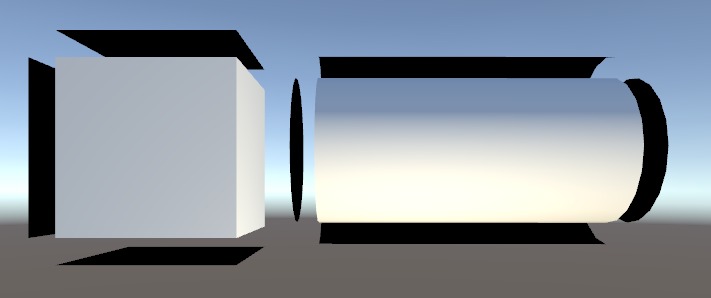
Take a good look at the screenshot above, from the scene in the Unity Package. Notice anything off? One of the downsides of “blowing up” your meshes with vertex extrution, is that very sharply angular models tend to “break up” the silhouette. This is important to be aware of if you wish to use this method in your work.
Code:
The first thing you’ll run into, is the Properties block. This is simply a way to add parameters to the inspector, when viewing the shader in Unity, like this:
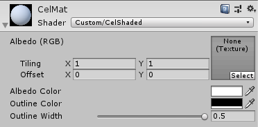
Although I have not used any textures in this demonstration, I left the feature in the shader, in case you want to use it for anything that doesn’t have to be a solid color.
Next there’s the Subshader block. This entire block tells the GPU “try this out, and if it doesn’t work, just skip it”. At which point your shader code is ignored and the FallBack shader at the bottom will be run instead (eg. “Diffuse” which is a Unity standard shader). If you ever mess around and nothing happens, try uncommenting the FallBack statement, as it may just be running that instead of your actual code. Fallbacks are just great if you don’t know whether a platform supports your shader or not, as they prevent your game from crashing.
Next there’s the CGPROGRAM block. This doesn’t use brackets, but instead ends when it says “ENDCG” further down. The initial CGPROGRAM block contains just the simple surface shader with the Lambert lighting model. What that means is really just that we start by rendering the original mesh, applying texture and lighting to it as we normally would.
However, going past that there’s a Pass block with another CGPROGRAM block inside it. The reason for this bit being encapsulated in a Pass, is because it contains a vertex and a fragment function (which we’ll get to in a moment), as well as the fact that the Pass block includes some functionality which we need for this shader to render properly.
Among this functionality is the following line:
Cull FrontThis command culls all of the front facing vertices, meaning that we’re rendering the “inside” of the mesh. The reason we do this (as we’ll get further into detail with as we go) is because we’re effectively rendering the mesh of the model one more time, on top of the already-rendered model. The reason I can do this in the second CGPROGRAM block without the whole thing turning black, is because the original CGPROGRAM automatically wrote to the depth buffer of the screen. The depth buffer is used to determine what is in front of what, and since the bloated mesh goes outwards from the original mesh, it will be behind the original.
The structs are nothing out of the ordinary, the inclusion of a color property will be used to set the eventual outline color:
 struct appdata
 {
     float4 vertex : POSITION;
     float3 normal : NORMAL;
 };

 struct v2f
 {
     float4 pos : SV_POSITION;
     fixed4 color : COLOR;
 };
The _Outline and _OutlineColor properties are used to set the width of the outline as well as the colour. In actuality, this means setting the level of extrusion by which the second render is done, as well as the colouring of the mesh:
 float _Outline;
 float4 _OutlineColor;
All of the logic to handle this kind of effect, is done within the vertex function, vert. The vertex function is where displacement of the vertices in the mesh are performed:
v2f vert(appdata v)
 {
     v2f o;
     o.pos = UnityObjectToClipPos(v.vertex);

      float3 norm = normalize(mul((float3x3)UNITY_MATRIX_IT_MV, v.normal));
     float2 offset = TransformViewToProjection(norm.xy);

     o.pos.xy += offset * o.pos.z * _Outline;
    o.color = _OutlineColor;
    return o;
 }
What happens in the first two lines is nothing out of the ordinary – the vertices from object space are being converted to the vertices in clip space with the UnityObjectToClipPos function.
The next line is pretty confusing if you are not familiar with the way matrix conversions work, however, to summarize:
float3 norm = normalize(mul((float3x3)UNITY_MATRIX_IT_MV, v.normal));Means that the normal of the object is being turned into a normal as a world coordinate (it has something to do with the “matrix conversion being inversely transposed,” just know that the command is necessary).
The second line is also a little convoluted, but fairly easy to grasp once you get the basics of it:
float2 offset = TransformViewToProjection(norm.xy);What this line does is generate a 2D “offset” value by taking the aforementioned world-position normal and projecting it onto clipping space – in other words, this is the conversion from world space to clipping space which allows for manipulation in relation to the screen. This offset value is then applied to the xy-coordinates of the vertices, multiplied by the z-coordinate (depth) and the _Outline property to generate a nice looking outline around the model (the colour is also applied here, to be accessed by the frag function afterwards). Basically, this is where we bloat the model:
o.pos.xy += offset * o.pos.z * _Outline;

o.color = _OutlineColor;
Notice in the multiplication that the o.pos.z value is also used as a parameter. What this does is act as a scaling factor to ensure that the thickness of the line remains the same across the model, no matter how far away the individual parts of the model are from the camera.
All the fragment function frag does, is apply the colour on the model:
 fixed4 frag(v2f i) : SV_Target
 {
     return i.color;
 }
To summarize the entire process, consider it as follows:
- An appdata struct containing the vertex positions and normals of the model, is passed into the vertex function
- The vertex function instantiates a v2f struct o, to contain the clip space coordinates for the converted vertices and the desired colour for the outline
- The object space coordinates (3D) of the vertices, are converted into clip space coordinates (2D) by the UnityObjectToClipPos function
- The object space normals on the model are being transformed into normalized worldspace normals
- Since the vertex positions in the v2f struct are in clip space, any modifications of these must also be in 2D. Therefore an offset value is found by projecting the worldspace normals onto clip space, via TransformViewToProjection, taking in the X- and Y-coordinates of the worldspace normals
- The offset is added to the vertex clip space coordinates, multiplied by the o.pos.z (to act as a scaling factor for consistent line thickness across the model), multiplied again by the _Outline scaling factor
- The colour is applied
- The whole v2f struct is passed onto the frag(fragment) function, which then prints the colour out