
Vertex and fragment shaders
Through my previous articles on shaders, I have worked exclusively with Surface functions to handle the shader logic. However, this function only handles certain aspects of rendering. What happens when you run your compiler, is that the surface function gets turned into what are called Vertex– and “per-pixel (or Fragment)”-functions. Compiling is basically like having a whole burger, then dropping it on the ground, witnessing its transformation into buns and patties before your very eyes. But what does vertex and fragment functions have in common with buns and patties, you ask? That we, too, can make them ourselves!

But why on Earth would we do that? “There’s so much that can be done with the surface shader alone!” To which I can only say that working with the surface function is like seasoning your burger. But working with vertex and fragment functions is like digging into the atoms of your burger, bashing them to perfection with the might of Krom!
Oh and to clarify some interchangeable terminology, it is common to call the vertex- and fragment functions which we write, vertex- and fragment shaders. I personally think this is a bit confusing, seeing as the shader (in my mind) is the whole file – which in this case, is what I’d call a vertex-fragment shader. It’s easier to talk about each component as a function, because that is common OOP terminology for a callable block of code, which is why I introduced them this way. But out in the real world, most people call them by their shader-name, which I will do from here on out. Just realize that the vertex shader is the vertex function, the fragment shader is the fragment function, and the vertex-fragment shader is an expression for the whole file, implementing both of these methods.
Vertex shader/function:
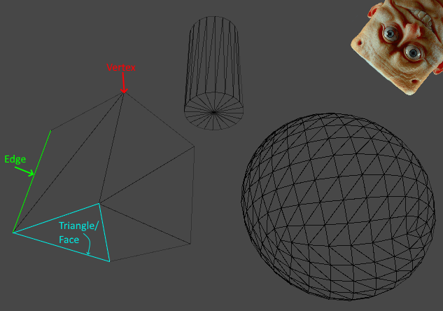
To understand a vertex shader, it is important to first understand what a vertex is. In 3D modelling, a vertex is a point in space. When two vertices (please do not call them vertici, I will destroy you) are connected, they form an edge. If three lines are connected, they form a triangle/face, which is how models are built – with tons of triangles. Any flat surface on geometry is referred to as a face, but any face is built out of triangles:
Hold on to your hats, because we’re about to get technical. What a vertex function does, is take the relative geometry of an object (where the vertices in the model are located, relative to each other – also called object space) and transforms those coordinates into points on the screen. In essence, it takes your 3-dimensional object and squishes it onto your 2-dimensional screen.
Since we can write our own vertex function, we can manipulate this process and transform the look of a model, by adding our own equations to the mix. It’s important to realize that morphing the location of the vertices at this point, does not affect how the object interacts with other objects in the physics – this is purely a visual effect.
The output structure of a vertex function is called appdata. It allows access to the following parameters (most of which we will use later):
struct appdata_full
 {
     float4 vertex    : POSITION;  // The vertex position in model space.
     float3 normal    : NORMAL;    // The vertex normal in model space.
     float4 texcoord  : TEXCOORD0; // The first UV coordinate.
     float4 texcoord1 : TEXCOORD1; // The second UV coordinate.
     float4 tangent   : TANGENT;   // The tangent vector in Model Space (used for normal mapping).
     float4 color     : COLOR;     // Per-vertex color
 };
Fragment shader/function:
Before I get into writing any code, I’ll also have to cover what a fragment shader is. The reason for this is that the vertex- and fragment shaders each cover an important part of the rendering process, and are commonly deployed together. Practically speaking, the functionality of the fragment shader is almost comparable to that of the surface shader. Examine the output structure for the fragment shader – called v2f (“vertex to fragment“):
struct v2f
 {
    float4 pos : SV_POSITION;
    float4 normal : NORMAL;
    float4 uv1   : TEXCOORD0;
    float4 uv2 : TEXCOORD1;
    float4 tangent : TANGENT;
    float4 color : COLOR;
 };
Compared to the Surface shader SurfaceOutput struct(s), this has access to some similar components, such as colour and normals, but none of the more powerful stuff such as Specular, Gloss, Alpha etc. This may seem a little weird – why choose that with less functionality? It really comes down to optimization and development time. The surface shader has a wider range of functionality (due to it considering the scene lighting), but it generates vertex- and fragment shaders upon being compiled, and may not run as fast as completely custom code. In truth, a surface shader is not truly a shader, but a bunch of commands creating your shader for you when compiling.

Vertex-fragment shader syntax:
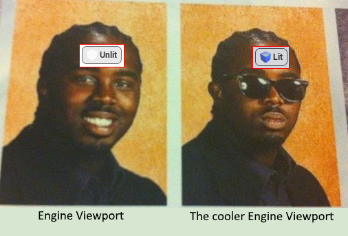
Now that I’ve covered the basics of each of these components, it’s time to look at the syntax of a standard vertex-fragment shader. The following code was generated by Unity, by doing the right-click > Create > Shader > Unlit shader. As mentioned above, it is “Unlit” because it doesn’t consider scene lighting:
Shader "Unlit/NewUnlitShader"
{
    Properties
    {
        _MainTex ("Texture", 2D) = "white" {}
    }
    SubShader
    {
        Tags { "RenderType"="Opaque" }
        LOD 100

        Pass
        {
            CGPROGRAM
            #pragma vertex vert
            #pragma fragment frag
            // make fog work
            #pragma multi_compile_fog

            #include "UnityCG.cginc"

            struct appdata
            {
                float4 vertex : POSITION;
                float2 uv : TEXCOORD0;
            };

            struct v2f
            {
                float2 uv : TEXCOORD0;
                UNITY_FOG_COORDS(1)
                float4 vertex : SV_POSITION;
            };

            sampler2D _MainTex;
            float4 _MainTex_ST;

            v2f vert (appdata v)
            {
                v2f o;
                o.vertex = UnityObjectToClipPos(v.vertex);
                o.uv = TRANSFORM_TEX(v.uv, _MainTex);
                UNITY_TRANSFER_FOG(o,o.vertex);
                return o;
            }

            fixed4 frag (v2f i) : SV_Target
            {
                // sample the texture
                fixed4 col = tex2D(_MainTex, i.uv);
                // apply fog
                UNITY_APPLY_FOG(i.fogCoord, col);
                return col;
            }
            ENDCG
        }
    }
}
Writing property declarations is the same as it is with any other shader, so that part we will not delve into. Additionally, the same rules of declaring the properties within the CGPROGRAM block to make them accessible, still applies.
The first new thing to consider in the code, is the fact that surrounding the CGPROGRAM block is a Pass block. A pass block causes the geometry of a GameObject to be rendered once:
Pass
{
   //CGPROGRAM goes here
}
This block is automatically added by the surface function, around any CGPROGRAM block containing one of such. However, it is possible to have multiple passes, which lets us render things in multiple steps, should that become necessary. AND, even with multiple passes, an eventual CGPROGRAM block with a surface function can still be declared to handle the lighting after all of that. But right now, we’ll stick to something simple.
Once inside the CGPROGRAM block, there’s the compiler directives (#pragma statement), as well as two interesting details:
#pragma vertex vert
#pragma fragment frag
// make fog work
#pragma multi_compile_fog

#include "UnityCG.cginc"
First of all, theres the vertex vert and fragment frag directives. These are name declarations, just as with the surface function, telling the compiler what functions to look for in the code, when performing the vertex and fragment operations.
The multi_compile_fog statement is an indicator for the compiler to create an additional variant of the shader, which looks for a “fog” setting in Unity, to apply the effect onto objects, if the effect is on. This doesn’t really concern us at the moment, just know that adding this statement enables your material to consider the fog in a scene.
The last line, #include “UnityCG.cginc”, tells the compiler to include the library specified in the quotation marks. This library contains the functions used by the vertex and fragment shaders, inside the CGPROGRAM block, and is a line that is normally generated by the surface function (read; don’t put this line inside a CGPROGRAM block containing a surface function, you will jank it up).

Next up, there’s the structs used by the vertex and fragment shaders:
struct appdata
{
	float4 vertex : POSITION;
	float2 uv : TEXCOORD0;
};

struct v2f
{
	float2 uv : TEXCOORD0;
	UNITY_FOG_COORDS(1)
	float4 vertex : SV_POSITION;
};
As with the surface shader, we should only declare the properties that we need, instead of listing all of them. Even unused properties declared here, will still be accessed at runtime, eating precious processing power like an olympic rower at a running sushi.
The UNITY_FOG_COORDS(1) line just handles the fog implementation mentioned earlier.
The most notable difference from the surface syntax, is that the properties being accessed, have a little : <Type declaration> suffix after them. These suffixed types are the actual system names for the variables being accessed, whereas the name and type (eg. float4 vertex) is the variable which we store that information in. We can pick the syntax apart like so:
<1.> <2.> : <3.>;
- The type of the variable which the shader will access
- The name of the variable which the shader will access
- The actual system variable from which the data is read, under the name and type specified in step 1 and 2. This name is not used again anywhere else in the code.
To recap the types from earlier, here’s the two output structures for the vertex and fragment shaders again, with all of the possible variables shown:
//Vertex shader output structure
struct appdata_full
 {
     float4 vertex    : POSITION;  // The vertex position in model space.
     float3 normal    : NORMAL;    // The vertex normal in model space.
     float4 texcoord  : TEXCOORD0; // The first UV coordinate.
     float4 texcoord1 : TEXCOORD1; // The second UV coordinate.
     float4 tangent   : TANGENT;   // The tangent vector in Model Space (used for normal mapping).
     float4 color     : COLOR;     // Per-vertex color
 };

//Fragment shader output structure
struct v2f
 {
    float4 pos : SV_POSITION;
    float4 normal : NORMAL;
    float4 uv1   : TEXCOORD0;
    float4 uv2 : TEXCOORD1;
    float4 tangent : TANGENT;
    float4 color : COLOR;
 };
Why do I show you these again? Because all of the actual system variable names are the same – the same system data is accessed in both of these output structures, with the exception of POSITION being replaced by SV_POSITION in the fragment structure. This is important, because it indicates that the coordinates have changed and are now stored in a different system variable.

Describing the actual transformation process happening from the vertex shader to the fragment shader, is very complex and outside the scope of this tutorial. Luckily, it is not necessary to understand these processes to understand what has happened.
Earlier I mentioned the process of “squishing” a 3D object into 2D space, and it is between these two shaders that this process happens. But to make matters a little weird, even though the information is now squished into 2D in the fragment shader, it is not the final image being displayed on the screen just yet. Here are the steps taken to get into “screen space” – the information which we display on the monitor:

There’s a lot of steps here, but vertex and fragment shaders only really work with two of them:
- (1) Local Space: Vertex shader goes here
- (4) Clip Space: Fragment shader goes here
Luckily, we don’t have to remember most of this stuff, but it is good to know what stages we operate on when developing new shaders, as it determines what can be accessed and modified at each stage.
Moving past the structs in the code example, we run into the property declarations. These look like they do in the previous articles, with one little exception:
sampler2D _MainTex;
float4 _MainTex_ST;
What’s happening here is that both of these declarations, refer to the same property! While _MainTex refers to the texture used by the vertex shader, _MainTex_ST exposes that same property to the fragment shader. What gets a little funky about this, is that the texture – in both shaders – is referred to as _MainTex, so the fragment shader drops the _ST suffix when writing the code. Which brings us to the code for the shaders themselves:
//Vertex shader
v2f vert (appdata v)
{
	v2f o;
	o.vertex = UnityObjectToClipPos(v.vertex);
	o.uv = TRANSFORM_TEX(v.uv, _MainTex);
	UNITY_TRANSFER_FOG(o,o.vertex);
	return o;
}

//Fragment shader
fixed4 frag (v2f i) : SV_Target
{
	// sample the texture
	fixed4 col = tex2D(_MainTex, i.uv);
	// apply fog
	UNITY_APPLY_FOG(i.fogCoord, col);
	return col;
}
What is seen here, is the barebones functionality needed to apply a texture to an unlit shader. There is also a little bit of fog-stuff, but we’ll breeze past those bits. First, let’s look at the vertex function without the code inside:
//Vertex shader
v2f vert (appdata v)
{
    //Code goes here
}
First of all, there’s the vert name which we saw declared in the compiler directive, as the name for our vertex shader. This is just a name identifier and can be called whatever you want, as long as it matches the one you wrote in the compiler directive.
Secondly, this function returns a variable of the v2f type and takes a parameter of the type appdata. These were the two output structures we covered earlier, which is important to remember when we examine the code inside of the vertex shader:
v2f vert (appdata v)
{
	v2f o;
	o.vertex = UnityObjectToClipPos(v.vertex);
	o.uv = TRANSFORM_TEX(v.uv, _MainTex);
	UNITY_TRANSFER_FOG(o,o.vertex);
	return o;
}
Let’s go line by line. Since the vertex shader must return a v2f variable, we create one and call it “o”. Next we begin to modify the components of o, as specified in the v2f struct earlier (here it is again, so you don’t get tenosynovitis from all the scrolling):
struct v2f
{
	float2 uv : TEXCOORD0;
	UNITY_FOG_COORDS(1)
	float4 vertex : SV_POSITION;
};
We have access to the uv coordinates and the vertices of the mesh. We also have access to the fog stuff, but we don’t think much about that. The point is, going into the vertex function code again, there’s these two lines:
o.vertex = UnityObjectToClipPos(v.vertex);
o.uv = TRANSFORM_TEX(v.uv, _MainTex);
As you can see, we modify the uv coordinates and the vertices in the vertex function – the two things exposed in the struct.
UnityObjectToClipPos takes each vertex and transforms them from local space into clipping space, before storing the result in o.
TRANSFORM_TEX performs a similar operation, which aligns the texture with the newly transformed vertices, so it is displayed correctly.
Then the fog-stuff is applied and the result is returned. What’s interesting to note, is that there is no call to the fragment function or anything else at the end of the vertex function. This logic is already handled for us, so long as we make sure to return the result from the vertex function. Then the fragment function automatically recieves this as its parameter:
//Fragment shader
fixed4 frag (v2f i) : SV_Target
{
    //Code goes here
}
As you’ll notice here, the v2f struct is now taken as a parameter by the frag function, so that it may work with what was calculated.

Additionally, the fragment function returns a fixed4 (because it returns the RGBA of the pixel) and there’s a little : SV_Target suffix at the end of its declaration. This indicates where we’re sending the results, but we won’t deal with any further steps in this tutorial, as that is quite unnecessary for working with the basics.
The actual code inside the fragment shader is super simple:
fixed4 frag (v2f i) : SV_Target
{
	// sample the texture
	fixed4 col = tex2D(_MainTex, i.uv);
	// apply fog
	UNITY_APPLY_FOG(i.fogCoord, col);
	return col;
}
Would you look at that, it’s the good old tex2D function returning to us! And it still does what it always did, which is look at the texture and uvs to find out what colour the pixel should have. Aaand more fog application, and finally the result is returned.
All that theory, just to explain how the texture gets on the model, huh? But this is where the fun begins! Because now that we know what each of these functions can access, we can modify (read; mess up) what is displayed on the screen, by changing the values at each step!
Object space:
I previously mentioned object space as the coordinates of each vertex, in relation to each other. To better understand what that means and to write our first custom vertex-fragment shader, write the following code:
Shader "Custom/ColourVF"
{
	SubShader
	{
		Pass
		{
			CGPROGRAM
			#pragma vertex vert
			#pragma fragment frag

			#include "UnityCG.cginc"

			struct appdata
			{
				float4 vertex : POSITION;
			};

			struct v2f
			{
				float4 vertex : SV_POSITION;
				float4 color : COLOR;
			};

			v2f vert (appdata v)
			{
				v2f o;
				o.vertex = UnityObjectToClipPos(v.vertex);
                                o.color.r = v.vertex.x;
				return o;
			}

			fixed4 frag (v2f i) : SV_Target
			{
				fixed4 col = i.color;
				return col;
			}
			ENDCG
		}
	}
}
This is a vertex-fragment function which takes no properties, but applies colour to a surface, based on the x-coordinate of the vertices in the model. Here is a bunch of Unity’s default shapes with the shader applied to them:
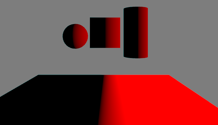
This is not a trick of the light. What happens here, is that the colour property is defined by the internal x-value of the individual vertices:
o.color.r = v.vertex.x;If the values are above 1, the red channel will be above 1. Likewise if the values are below zero, the red channel will be below zero (which is just black). Depending on the mesh, the positive and negative range of the vertices may be greater or lower, as there may be more or less vertices in the mesh. The application of the colour is done by the fragment function, by simply accessing the RGB values stored in the color property of the v2f structure passed to it:
fixed4 col = i.color;To illustrate how vertices are numbered, try slapping the following C#-script onto your objects:
public class MeshData : MonoBehaviour {
	void Start () {
           //Fetch mesh and save in array
           Mesh mesh = GetComponent<MeshFilter>().mesh;
           Vector3[] vertices = mesh.vertices;

           //Output array
           foreach(Vector3 v in vertices)
           {
               Debug.Log(v);
           }
        }
}
This will poop out the value range of your mesh’s vertices. On a default Unity plane, the values range from -5 to 5:

This means we can straight up add a 5 to the colour calculation like this:
o.color.r = v.vertex.x + 5;To get this result:
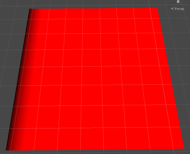
It is quite clear that the zero-values have been pushed to the edge of the mesh. Additionally, we can use a division to stretch out the effect across the mesh, for a smoother transition between the values:
o.color.r = (v.vertex.x + 5) /20;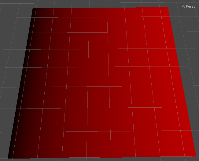
You can also modify all three of the RGB channels to use the XYZ values of each vertex, which will give you a fancy album cover:
o.color.r = v.vertex.x;
o.color.g = v.vertex.y;
o.color.b = v.vertex.z;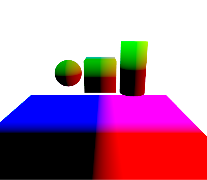
Vertex-surface shader:
As I may have hinted earlier, it is possible to whizbang the vertex and surface shaders together. I’ll illustrate how we can modify the vertices of a mesh before displaying it, so that it looks like it sat on a bicycle pump:
Shader "Custom/Normal Extrusion" {
	Properties{
	  _Color("Color", Color) = (1,1,1,1)
	  _Amount("Extrusion Amount", Range(-1,1)) = 0.5
	}
		SubShader{

		  CGPROGRAM
		  #pragma surface surf Lambert vertex:vert
		  struct Input {
			  float2 uv_MainTex;
		  };

		  float _Amount;

		  void vert(inout appdata_full v) {
			  v.vertex.xyz += v.normal * _Amount;
		  }

		  float4 _Color;

		  void surf(Input IN, inout SurfaceOutput o) {
			  o.Albedo = _Color.rgb;
		  }
		  ENDCG
	  }
		  Fallback "Diffuse"
}
There’s a few important things to notice here, as the inclusion of a surface function means a lot of the aforementioned elements will be added automatically. First of all, there’s no Pass block surrounding the CGPROGRAM. Second of all, there’s this line:
#pragma surface surf Lambert vertex:vertIt is a normal surface shader declaration with the Lambert lighting model, but there’s an added vertex : vert at the end. This tells the surface function to look for the vertex function named “vert”, as ours is called.
Then there’s the vertex function itself, which has changed a little bit in its syntax:
void vert(inout appdata_full v) {
	v.vertex.xyz += v.normal * _Amount;
}
First of all, notice how the function no longer returns anything – it is void. This is because the parameter now has changed from the previous “appdata” structure, to appdata_full, acting as an inout parameter, where changes to any of its values will automatically be reflected everywhere that the datatype is used – meaning we do not have to return it.
Then there’s the actual vertex modification:
v.vertex.xyz += v.normal * _Amount;Before I go on, let’s consider what I want to do here. In order to “blow up” a mesh, I will have to multiply the positions of the vertices by some amount. Additionally, I want this multiplication to move the vertices outwards, so I can use the surface normals for that (as you may remember from my article about lighting models – the surface normals always point out at a 90 degree angle to the surface of the mesh). And that is exactly what happens here. The vertices are moved by some amount, in the direction of the surface normals.
Now what does that look like? My friend Emil has provided a neat 3D model for me to break apart. Behold, the spherical might of the-… Some species of three-dimensional bear:
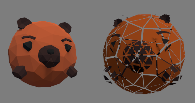
On the left side is the unmodified mesh, using Unity’s Standard surface shader. On the right is the same mesh, but using the extrusion shader which I just wrote, cranking the multiplier up to 1. The result is that each triangle moves some distance, in the direction that the triangle is facing.
That pretty much covers the basic syntax stuff for vertex-fragment shaders and vertex-surface shaders! There’s still some fundamentals I have yet to cover, like different types of passes (or working with multiple passes), but we’re slowly working up to a point where we can really get creative with this stuff. I will come up with some more interesting examples of what can be done as we move along.