Shaders and lighting models
As I covered in the previous article about shader anatomy, there are a few different lighting models to choose from, if you are not creating your own. Depending on the model, you will have access to different properties in your surface function.
But what exactly is a lighting model, and how can we use them for cool stuff? Because that’s really what we’re here for, all the cool beans.
A lighting model is really just an algorithm, which looks at a handful of things to determine – pixel by pixel – how bright a material should be and what colour it should have. The simplest lighting models – such as the Lambert model used in the previous article – only looks at the angle of a surface relative to the light source. Don’t worry, it’s math, but it’s the fun kind.
Surface Normals:
Before we get into the lighting models themselves, there’s one central aspect to all of them that we need to cover: the surface normals!
I previously mentioned that even the simplest lighting models still consider the angles of the the mesh being rendered, relative to the light source. And such an angle is described by a funny little thing called a surface normal – which is a vector sticking out of any surface at a 90 degree angle:
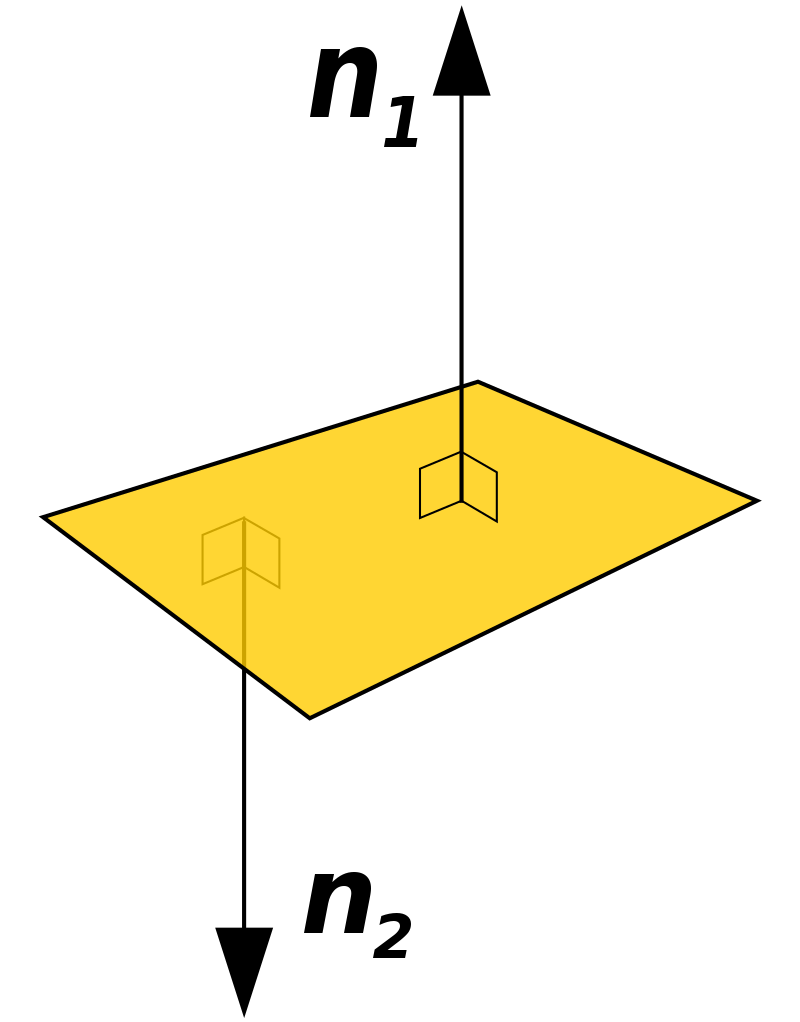
This is called a surface normal, because it is the “line normal to a surface.” A shader calculates how each individual pixel should be displayed, not just the colour of each polygon on a surface. Which means that – yes – there exists one normal per pixel, not per surface angle. The pixel normal direction is simply derived from the angle of the surface which the pixel rests on.
But we don’t have to be satisfied with just taking the information from the mesh. We can modify the normals however we want, to create the illusion of geometry – for freakin’ free (computationally, that is)! How can we do such magic you ask? With normal maps is how!
A normal map is a texture with a specific form of colour coding, to determine the angle of the normal on each pixel, instead of taking those values from the geometry of the model.

As illustrated, the three different RGB values are used to determine the direction of the normal, relative to the surface of the geometry.
This may get a little confusing if you’re not well versed in vectors. Just know that you can change how lighting is reflected off of geometry, by applying a texture to handle that part for you. Plus the code needed to apply a normal map to a texture, is very similar to applying a regular texture (as covered in the previous article):
First you’ll need to declare a property to handle your normal map. This is a texture, but note how the default value isn’t “white” as when applying a regular texture, but is instead “bump”:
_normTex("Normal texture", 2D) = "bump" {}This change is done because we’re not going to display the actual colours of the normal map, but rather use them to calculate the normals, and with this keyword we indicate that we’re indeed going to use it for that. The “bump” keyword comes from people originally calling this bumpmaps instead of normalmaps. Actually – to be completely factual – normal maps are different (better), but are considered to be the same in practice. The primary difference is that bumpmaps use grayscale values (black to white) whereas normalmaps use RGB values (red, green, blue).
Next we will need the UV values for the normal texture, so those will have to be declared in the Input Struct:
float2 uv_normTex;Then once again declared underneath the Input struct, to let the CGPROGRAM block access it:
sampler2D _normTex;And finally, we can modify the normals by writing the following line inside the surface function:
o.Normal = UnpackNormal(tex2D(_normTex, IN.uv_normTex));As in the previous article, both the UnpackNormal and tex2D functions are part of the CG library. Also notice how unlike in the previous article, this time we do not specify that we’re accessing just the RGB values from the tex2D call, but instead use all of the information it returns, to calculate the normals via the call to UnpackNormals.
Lambert:
As was mentioned at the beginning, the Lambert lighting model is on the simpler end. It compares only the surface angle and the angle of the light-source when performing the calculation.

In the above illustration, the viewer is also present, but the Lambert lighting model only uses the Normal (n) and the Source (s) vectors. When the angle between the two vectors approaches zero degrees, the lighting is the most intense. But when the angle exceeds 90 degrees, the surface is no longer affected by the light source, as the light is now behind it.
Also, did you know that this lighting model was written by some guy named Johann Heinrich Lambert back in 1760?! Some serious brainpower.
To use this lighting model in your surface function, it has to be written in your compiler directive like so:
#pragma surface surf LambertAs was briefly covered in the previous article, this gives you access to a handful of properties within the surface function, such as the albedo, emission, normals etc.
But what if we’re REALLY serious about our lighting models? Like Lambert-level serious. In that case, it is possible to specify a custom lighting model! If you’re still learning about shaders, doing this instead of using the built-in stuff is super overkill. But if you want a forehead like Mr. Johann, this is a good place to get started.
First of all, you’ll need to write a compiler directive which uses the name you want for your custom model:
#pragma surface surf GiganticForeheadNext you’ll need to write the lighting model. This should be written right after the compiler directive. I’m just going to paste the whole thing out and then we’ll go through it one step at a time:
half4 LightingGiganticForehead(SurfaceOutput s, half3 lightDir, half atten) {
	half NdotL = dot(s.Normal, lightDir);
	half4 c;
	c.rgb = s.Albedo * _LightColor0.rgb * (NdotL * atten);
	c.a = s.Alpha;

	return c;
}
Let’s begin with the function declaration. Notice that the name is LightingGiganticForehead. This name has to be identical to the one declared in the compiler directive, prefixed by the keyword Lighting to identify it as a lighting model.
Next there’s the SurfaceOutput s parameter. This output model is what provides access to the albedo, emission, normals etc. and is what the built-in Lambert model uses as well.
The half3 lightDir parameter references the direction of the light in the scene. This is pretty much required, because you would be hard pressed to write a lighting model that doesn’t consider the light in the scene.
The third parameter, half atten indicates the attenuation of the light in the scene. To repeat that in mortal tongue, it is the light intensity – or how fast the light ‘decays’ per distance travelled.
Going past the block declaration and into the actual code of the lighting model, we run into this fancy line of code:
half NdotL = dot(s.Normal, lightDir);This value is the dot product between the surface normal (which is the one sticking out at a 90 degree angle from the geometry) and the light direction. For those unfamiliar with what a dot product of two 3D vectors happen to be, it is the cosine of the angle between the vectors. What’s cool about cosine is this:
- Two vectors that are perfectly aligned will return 1
- Two vectors at an angle in the same direction will be between 1 and 0
- Two vectors at a 90 degree angle will return 0
- Two vectors at an angle in opposite directions will be between 0 and -1
- Two vectors perfectly opposite will return -1
If you want to know exactly why this is, I recommend giving Khan Academy a visit for some good old trigonometry. This is not a requirement, but it does feel nice to know that you, indeed, are not exercising black magic when you write that line of code.

After this line, there’s another three to be considered in tandem:
half4 c;
c.rgb = s.Albedo * _LightColor0.rgb * (NdotL * atten);
c.a = s.Alpha;
The first line half4 c, declares a variable containing four half-values, which is useful for storing stuff like XYZW – or in our case – RGBA (the A is the alpha channel, can be used for transparency if you want).
The second line consists of a few interesting components. In short, this is where we determine the RGB values for the pixel.
- s.Albedo means taking the colour of the surface, which is what we are modifying with the lighting model.
- _lightColor0.rgb is a built-in variable from Unity, which takes the colour values of all of the lights in the scene. Multiplying with this is the same as we did in the previous article, when manually multiplying the texture with some colour.
- NdotL multiplied with atten is where the light is applied. If either of these are zero, the whole expression becomes zero and the colour of the pixel turns black. So if the surface is no longer at an angle where it receives light, or if the light source is too far away, is when that will happen.
Finally, the result of these calculations is applied by simply returning c at the bottom of the lighting model.
And boom, you can now use this in your surface function, just as we have done with the built-in Lambert model. Writing custom models like this allows for modifications. Although rarely needed, it is a great way to understand what is going on. For example, if you comment out the last parenthesis where the lighting is added, your lighting model will completely ignore all of the lighting in the scene.
Blinn-phong reflection:
While the Lambert model is nice and simple, it only really looks good on diffuse (non-shiny) objects. If you want something to look realistic, it will require additional calculations.
This next lighting-model has a strange name, because it was developed by two different people, over two iterations. The original model was simply named the Phong reflection model, invented by Phong Bui-Tuong in 1975. What this model does, is compare the surface normal and the light direction, to create a new vector for the “reflected ray.” It is then the angle between the viewer and this reflected ray which determines the intensity of the light on that pixel:

However, there’s a fair few calculations involved in this process, which another guy named Jim Blinn realized. So he made some modifications and smacked his name right on there; boom, Blinn-phong was born!

Fun fact; Jim Blinn actually worked on the visuals for the original Cosmos series by Carl Sagan, so you have likely encountered his work before, without realizing it.
The Blinn-phong reflection model works with a half-way vector between the light source and the viewer:

What’s neat about this little trick, is that you can get the half-way vector by simply adding the other two vectors together. So what was previously an expensive calculation, is turned into simple addition. Assuming the following:
- H = Halfway vector
- S = Lightsource vector
- V = Viewer vector
The halfway vector is simply:
H = S + V
Which is:
H.x = S.x + V.x
H.y = S.y + V.y
H.z = S.z + V.z
The Blinn-phong model then measures the angle between this halfway vector and the surface normal vector. The end result is visually similar to the original Phong model, but runs way faster, as addition is cheap to do in the world of computers.
Now that we know how it works, it is time to build one ourselves! Once again, I will start by pasting in the whole thing, then go through one element at a time:
#pragma surface surf BasicBlinn

half4 LightingBasicBlinn(SurfaceOutput s, half3 lightDir, half3 viewDir, half atten) {
		half h = normalize (lightDir + viewDir);

		half diff = max(0, dot(s.Normal, lightDir));

		float nh = max(0, dot(s.Normal, h));
		float spec = pow(nh, 48.0);

		half4 c;
		c.rgb = (s.Albedo * _LightColor0.rgb * diff + _LightColor0.rgb * spec) * atten;
		c.a = s.Alpha;

		return c;
		}
First off there’s the compiler directive. There’s really nothing new here.
In the function declaration, we’re still taking the same parameters as in the custom Lambert model, with one addition: half3 viewDir. As the name suggests, this parameter lets the lighting model access the angle of the viewer. Before I get ahead of myself, now that we’re using the angle of the viewer, I want to give you a good picture of what that actually means. Consider the following illustration:

What you see here is that the viewDir vector is perpendicular to the “surface” of the viewer/screen. The reason it points towards the viewer and not into the scene however, is because we’re using it to determine how much a normal in the scene is facing the viewer. Should a vector perfectly aling with the viewDir vector, their dot product will result in 1, whereas it would have been -1 if the viewDir pointed inwards (which would be harder to work with).
Going back to the code, take a look at the first line:
half h = normalize (lightDir + viewDir);This is where the halfway vector is calculated, by adding the light direction and view direction together. However, there is one more step which was not mentioned in the model description – normalize. What a vector normalization does, is take a vector pointing in any direction, then reducing it to the length of 1. Nice and confusing, since a “surface normal” is something entirely different (as it is in the context of geometry, whereas this is in the context of vector mathematics). We do perform this operation because we will be using the vector for some calculations, and want to make sure all of our vectors have the same length. Not doing this may yield some wacky results.
Next there’s this line:
half diff = max(0, dot(s.Normal, lightDir));What we do here, is calculate the diffuse value for the colouring, which is based on the angle between the surface normal and the light direction. By using the max function, we ensure that we won’t get a result that is less than zero, as the function returns the maximum value between the parameters given to it (which will be zero, if the light is at an angle more than 90 degrees from the surface normal).
Then there’s what is called the specular falloff, which I haven’t really mentioned before now, but it is a way to calculate how quickly light will disperse across the surface (eg. the size of the “shine” effect at the brightest points).
To calculate the specular falloff, two calculations have to be made. The first one is based on the max value of the dot product between the surface normal and the halfway vector, once again clamped at 0:
float nh = max(0, dot(s.Normal, h));The second part of the specular falloff calculation is this line:
float spec = pow(nh, 48.0);It takes the value of the aforementioned nh dot product, and lifts it up to the power of 48 (which is Unity’s standard value, you can change this to whatever you want). But hold up! Remember what the dot product is? It’s the cosine of the angle between the vectors. Which means – yes, it’s below 1 most of the time. And any number less than one, uplifted to the power of anything, will quickly disperse as the multiplication of – say, 0.5 times 0.5 gives 0.25 – the pow operation actually decreases the value! And that is why the light “falls off” and doesn’t cover the whole surface of the object with one big shine.
With these calculations done, we can combine it all in a single statement, to calculate the light of each pixel:
c.rgb = (s.Albedo * _LightColor0.rgb * diff + _LightColor0.rgb * spec) * atten;As with before, there’s the colour of the colour of the surface (s.Albedo) multiplied with the colour of the scene lights (_LightColor0.rgb) multiplied with the diffuse value (diff).
These are then added to the colour of the scene lights (_LightColor0.rgb) again, multiplied with the specular falloff (spec) to give it that shine.
Finally, all of this is multiplied with the light attenuation (atten) so that the distance to the lightsource will diminish the effect, until it is too far away and the value of atten is zero – causing c.rgb to become zero as well.
Then the alpha is applied to c and the result is returned.
Physically based rendering:
With the two most common lighting models covered, it’s time to dive into the deep end. While we’re not quite going to go to the spooky mariana trench depth that is raytracing, we’re going fairly deep with physically based rendering (PBR).
Physically based rendering is not a single lighting model such as the ones described above, but rather a sequence of calculations which attempt to create realism, by emulating multiple physical properties in materials as they are seen in real life. For your shader to be considered “physically based,” it would have to simulate all of the following properties (feel free to just skim past these points):
- Reflection
Reflection is calculated by drawing rays from the viewer to the reflective surface and then calculating where it bounces off. This is the reverse calculation to lighting.
- Diffusion
Diffusion examines how colour and light are distributed across a surface, by considering what light is absorbed, what light is reflected and how.
- Translucency and Transparency
Translucency and transparency examines how light can move through objects, to render them fully or partly see-through.
- Conservation of Energy
The conservation of energy is a concept that ensures an object never reflects more light than it receives – unless an object is a perfect mirror finish, then it will absorb light depending on the surface – however, some light will always be reflected and available to light other objects.
- Metallicity
Metallicity considers the interaction of light on shiny surfaces – and the highlights and colours that are reflected. Metals tend to be highly reflective with very little in the way of diffuse light.
- Fresnel Reflectivity
Fresnel reflectivity examines how the reflection on a surface becomes stronger towards the edges. This is how real-world reflection works on curved surfaces.
- Microsurface Scattering
Microsurface scattering is not unlike bumpmapping, and suggests that most surfaces contain grooves or cracks that will reflect the light at different angles, other than those dictated by a regular surface.

That’s quite a lot! However, you don’t really have to remember any of that, as the implementation of these principles is really easy! Similar to the Lambert and Blinn-phong lighting models, Unity has two other built-in models:
- Standard PBR
- Standard Specular PBR
Unlike the Lambert and Blinn-phong models, both of these models appear very visually similar. There are some differences between them and how they approximate realism however, which I will elaborate on below.
Standard PBR:
The Standard PBR is considered the less-accurate-but-cheaper version of the two. Let’s take a look at a super barebones standard PBR shader which doesn’t do anything other than not crash (I’m lying, it does do some things, but we’re not rendering a Picasso anytime soon):
Shader "Custom/StandardPBR" {
	Properties{
		_Color("Color", Color) = (1,1,1,1)
		_MetallicTex("Albedo (RGB)", 2D) = "white" {}
		_Metallic("Metallic", Range(0,1)) = 0.0
	}
		SubShader{
			CGPROGRAM

			#pragma surface surf Standard

			sampler2D _MetallicTex;
			half _Metallic;
			fixed4 _Color;

			struct Input {
				float2 uv_MetallicTex;
			};

			void surf(Input IN, inout SurfaceOutputStandard o) {
				o.Albedo = _Color.rgb;
				o.Smoothness = tex2D(_MetallicTex, IN.uv_MetallicTex).r;
				o.Metallic = _Metallic;
			}
			ENDCG
		}
			FallBack "Diffuse"
}
For the most part,this looks almost identical to what we have worked on before. However, there’s a couple of new elements to consider:
#pragma surface surf StandardThe name of the lighting model must be set to “Standard“.
void surf(Input IN, inout SurfaceOutputStandard o) {
		o.Albedo = _Color.rgb;
		o.Smoothness = tex2D(_MetallicTex, IN.uv_MetallicTex).r;
		o.Metallic = _Metallic;
}
The inout parameter for the Standard lighting model is SurfaceOutputStandard. This type exposes a bunch of new parameters which we can use. In this example, I have chosen to modify the “Smoothness” and “Metallic” properties. Let’s take a closer look at the second line – this is where stuff gets really interesting:
o.Smoothness = tex2D(_MetallicTex, IN.uv_MetallicTex).r;In this line, the “smooothness” of a pixel is determined by the red-channel of the texture. What this means is that the value stored in the red-channel of the texture used, determines what pixels should be reflective and to what degree. Higher values mean higher reflectivity. Which brings us to the second line:
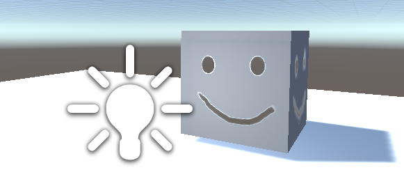
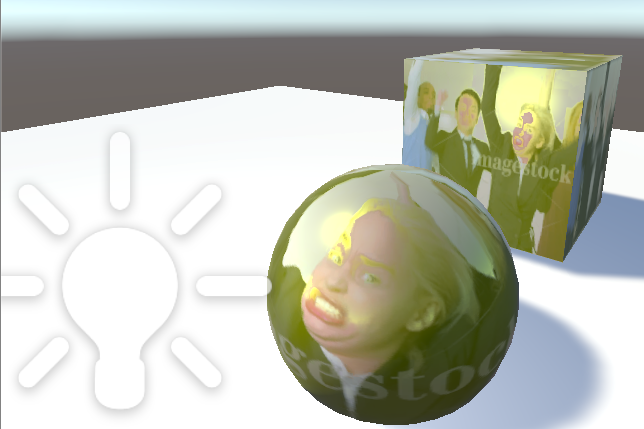
o.Metallic = _Metallic;The value here is from the slider property specified at the top. This is a multiplier which dictates just how much the reflective areas, should reflect. To test this, I put a material using the shader onto a cube, then slapped on this majestic piece of art as my metallic texture:

I cranked the “Metallic” value all the way up to 1, dropped a spotlight in front of it and voilá:
Alright, so there’s a few things going on here. First of all, you may notice that the black areas of the texture are not black. This is when we have to remind ourselves that this is not an albedo texture, but one used to indicate the degree of reflection. With the metallic value at 1, the black areas are simply matte, whereas the white areas reflect the skybox almost perfectly. There is some slight interpolation going on around the edges as well, with the white outline around the eyes and mouth. This is not something we have programmed directly, but one of the things that occur when doing physically based rendering, as the visuals undergo additional calculations to behave realistically.
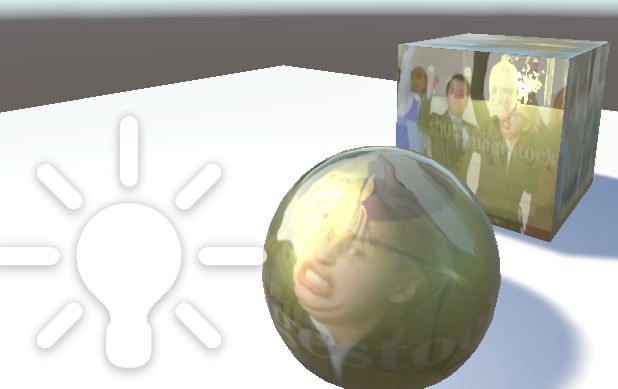
If we turn the metallic value half-way down or all the way to zero, the reflectivity of the metallic texture becomes gradually less apparent:
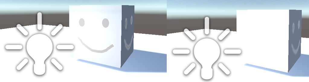
As you can see, the “metallic” value effects everything, but the metallic texture helps amplify the effect as a multiplier. And even with metallic at zero, less illuminated surfaces are still effected by the metallic texture. This opens up a lot of possibilities for weird and fancy effects, once you realize how everything interacts in PBR. I recommend really just fiddling around with the different parameters which you can access with the
Standard specular PBR:
For the Standard Specular PBR shader, the code is pretty much the same:
Shader "Custom/StandardSpecularPBR" {
	Properties {
		_Color ("Color", Color) = (1,1,1,1)
		_MetallicTex ("Albedo (RGB)", 2D) = "white" {}
		_SpecColor("Specular colour", Range(0,1)) = 0.0
	}
	SubShader {
		CGPROGRAM

		#pragma surface surf StandardSpecular

		sampler2D _MetallicTex;
		half _SpecColor;
		fixed4 _Color;

		struct Input {
			float2 uv_MetallicTex;
		};

		void surf (Input IN, inout SurfaceOutputStandardSpecular o) {
			o.Albedo = _Color.rgb;
			o.Smoothness = tex2D(_MetallicTex, IN.uv_MetallicTex).r;
			o.Specular = _SpecColor.rgb;
		}
		ENDCG
	}
	FallBack "Diffuse"
}
Let’s look for differences from the Standard PBR shader. First there’s the compiler directive, where the lighting model has changed:
#pragma surface surf StandardSpecularBy setting the lighting model to StandardSpecular, the output structure of the surf function has also changed:
void surf (Input IN, inout SurfaceOutputStandardSpecular o)
{
   //Code goes here
}
The o.Metallic parameter does not exist in the specular output structure (we can’t call it in the surf function) – instead the parameter is o.Specular. The difference between these two, is that the o.Specular parameter can take more than just a value – it can take three; RGB.
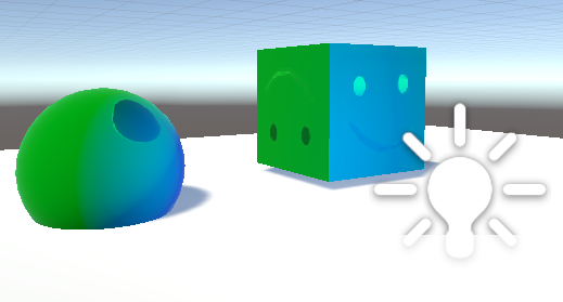
So what is the actual difference, in practice? It can be hard to tell at a glance, but the Standard Specular PBR setup lets the reflected light be coloured in accordance to the RGB values given But more so than that, it allows for that reflection to be a different colour than the texture underneath it. In the following picture, I’ve set the base albedo to green, and the specular colour to blue:
This becomes even more evident if we take a texture for our albedo, rather than just a single colour. Unfortunately, my fantastic artpiece does not have a lot of colours in it, so I decided to go ahead and slap some stock photo on there (I also changed the metallic texture to be the same as the albedo texture, to really make it shine). Here’s the change, to make your life a little easier:
Shader "Custom/StandardSpecularPBR" {
	Properties
	{
	    _AlbedoTex("Albedo (RGB)", 2D) = "white" {}
		_Color("Color", Color) = (1,1,1,1)
		_MetallicTex("Albedo (RGB)", 2D) = "white" {}
		_SpecColor("Specular", Color) = (1,1,1,1)
	}

		SubShader
		{

			CGPROGRAM
			#pragma surface surf StandardSpecular

			sampler2D _AlbedoTex;
			sampler2D _MetallicTex;
			fixed4 _Color;

			struct Input {
				float2 uv_MetallicTex;
				float2 uv_AlbedoTex;
			};

			void surf(Input IN, inout SurfaceOutputStandardSpecular o) {
				o.Albedo = tex2D(_AlbedoTex, IN.uv_AlbedoTex).rgb;
				o.Smoothness = tex2D(_MetallicTex, IN.uv_MetallicTex).r;
				o.Specular = _SpecColor.rgb;
			}
			ENDCG

		}
			FallBack "Diffuse"
}
What’s fun here is that you can have a different metallic texture than your albedo texture. If put a different stock photo, we’ll get something like this:
That pretty much wraps it up for understanding the basics of PBR and the difference between the two standard PBR models which Unity uses. You may now go into the world and ruin people’s eyeballs with your excellent skills – as long as you don’t hold me accountable.