
Introduction to shaders
In a previous article, I talked about cel shaders and how to make your own. In this article I will walk you through the basics for shaders in general, for those of you who want a deeper understanding and explore the subject on your own. However, the focus of the article will be on understanding shaders, more so than writing them ourselves. The writing part will be covered in later articles.
Anatomy:
The best place to start is with the anatomy of the shader. A shader in Unity consists of two languages:
- CG – Nvidia’s “C for Graphics”
- HLSL – High Level Shader Language for DirectX
These are commonly referred to together as just CG/HLSL when talking Unity’s shader language preferences. Don’t worry, when we get to it, it’ll be very clear when we’re writing in one thing or the other.
While CG and HLSL has some elements of object-oriented programming, you will often find shaders requiring a more rigid structure than OOP languages such as C++, C# and Java. Because of this rigidity, it can feel like there is less wiggle room – and certain structural requirements must always be met, depending on what you are doing. This can be a little off-putting and strange for someone who is used to working with OOP principles – I speak from experience. If anything, I was reminded of my time doing Cisco certifications, working with machines that had practically zero tolerance for error and creative interpretation.
Fret not, however! Once we are acquainted with these requirements, what can be written inside these frameworks is only limited by your imagination (and your computer’s processing power)! And believe me when I say this; being able to code graphics directly this way, almost feel like a superpower. What you can do with your OOP logic, how it can interface with your shaders and manipulate the visuals on the screen, is one of the most liberating experiences I have had working with video games.

To begin with, I recommend opening up a project in Unity and downloading this basic shader. It is a modified version of the shader which Unity generates, when creating the “Standard Surface Shader”:
The reason I haven’t created a Unity project directly for this article, is because the first step of understanding shaders, is how to access them within your project. It’s not enough just dumping them into the asset folder and pulling them onto the object. You will have to create a new material, which then uses the shader. For now, create and select your material, then select the shader by clicking the following:
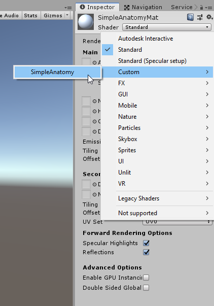
Why the shader appears under Custom > SimpleAnatomy, well get to in a moment. For reference sake, here’s the code from the shader, then I’ll go over each bit:
Shader "Custom/SimpleAnatomy"
{
	Properties{
		//Colour, defaults to white
		_myColour("Colour", Color) = (1,1,1,1)
	}

		SubShader{

			CGPROGRAM

			//Compilation directives
			#pragma surface surf Lambert
			/*
			   1) surface - indicates that it is a surface shader
			   2) surf - the name of the function containing the surface shader
			   3) Lambert - the lighting model used by the surface shader
			*/

			struct Input {
				float2 uvMainTex;
			};

	//CGPROGRAM property declarations
	fixed4 _myColour;

	/*
		Notice that the expected output is of the SurfaceOutput type.
		This is because of the Lambert lighting type, so always consider
		which lighting you use, to determine the output type.

	*/
	void surf(Input IN, inout SurfaceOutput o) {
		o.Albedo = _myColour.rgb;
	}

ENDCG
	}

    FallBack "Diffuse"
}
First of all, there’s the outer Shader block:
Shader "Custom/SimpleAnatomy"
{
    // The rest goes here
}
Notice anything familiar? The directory specified within the string, was where we found the shader in the drop-down menu on the material. Unlike most other scripts in Unity, this name does not have to be consistent with the name of the file, so you can call it whatever you want, creating your own directories if “Custom” doesn’t really suit your needs.
Next there’s the Properties block. This where you declare your “public fields,” which will appear in the Unity inspector on materials using the shader. This is great for external manipulation, as it also allows your scripts to interface with these properties. Here’s what property I have declared in the file:
	Properties{
		//Colour, defaults to white
		_myColour("Colour", Color) = (1,1,1,1)
	}
When declaring a property, there is a specific syntax that you must follow. Before I go into the different property types and what they look like when viewed in Unity, let’s deconstruct the syntax. Below is the first property from the code. And beneath that are four numbered <>-brackets, each corresponding to a syntax component in that property:
_myColour(“Colour”, Color) = (1,1,1,1)
<1.>(“<2.>”,<3.>) = (<4.>)
- The first component is the property name. This is not the name you will see in the Unity inspector on the material, but the name you must use when referring to the property in both the shader and in your other scripts accessing the shader.
- The second component is the property name as it will be show in the inspector. This is really just for readability (which is important!).
- The third component is the type declaration. There are six different types of properties than can be declared this way, each of which I will summarize below.
- The fourth and last component is the default value of the property, in case nothing else has been set in the Unity inspector or via another script.
Before I get into the property types, with just the one property declared in the shader using the Color type, inspecting the material gets you this:
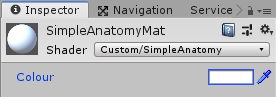
Note how the name corresponds to that given in the second property component in the shader (the “Colour” part). But there’s a handful more to be acquainted with. Here’s the whole list:
	Properties {
		_myColor ("Example Color", Color) = (1,1,1,1)
		_myRange("Example Range", Range(0,5)) = 1
		_myTex("Example texture", 2D) = "white" {}
		_myCube("Example cube", CUBE) = "" {}
		_myFloat("Example float", Float)= 0.5
		_myVector("Example vector", Vector)= (0.5, 1, 1, 1)
	}
If you paste these properties into the shader (you can do this if you want to, but the shader won’t actually use them unless specified later), they will show in the inspector like so:
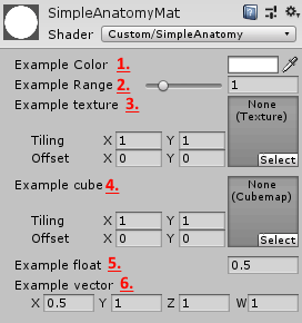
- Color – an RGBA/fixed4 value with a colorpicker in the inspector, set with the default value of white by specifying (1, 1, 1, 1) which indicates 255 in all values.
- Range – A specified range with a preset default value as 1.
- 2D – a texture, shows with tiling and offset options in the inspector, for further modification. Notice how the default value here is set a little differently than the others, with the { }-brackets at the end.
- CUBE – a cubemap for adding a cubemapped image, commonly used for skyboxes. As with the 2D datatype, take note of how the default value is initialized with { }-brackets as well.
- Float – simply a float.
- Vector – a four-dimensional vector XYZW, using floats for each value (so essentially a float4).
Moving past the Properties block comes the Subshader block.
SubShader
{
    //The shader logic goes here
}
It is within this that the logic of the shader will be written. The reason this block is not just straight up called the “shader block,” is because there can be multiple subshaders inside a shader. Which can be a little confusing at first, until you consider how this code will be compiled for the graphics card directly – and not all graphics cards are created equal. When writing a game for multiple platforms (or even just PCs in general), it may happen that one or more of your target platforms, uses a graphics card which doesn’t support a feature used by your subshader. In this case, the program will move on and try the next subshader, which may be written to be more generally compatible.
If all Subshader blocks fail, the shader won’t just crash, but can instead be redirected to a Fallback shader, written at the bottom of the code:
FallBack "Diffuse"Unity’s “Diffuse” shader is compatible with most platforms, so it may be a good choice. However, platforms who fall back to using this will not have any of the fancy graphics which you coded in your own shader, so this statement is really just the last-resort solution to prevent the game from crashing. Additionally, if your shader fails while developing it, you may not notice, because it just uses the Diffuse shader instead of your own. If you are making changes to your code and can’t understand why they’re not showing in Unity, try to comment out the Fallback statement and see if it crashes.
Inside of the Subshader block is another block, which uses a slightly different syntax: The CGPROGRAM – ENDCG block. This does not use brackets, but instead works like this:
CGPROGRAM
    // CG code goes here
ENDCG
As was referenced at the start, this is where we transition from HLSL into CG code. Everything written between these two keywords, will be interpreted by the compiler as CG code, whereas everything outside will be interpreted as HLSL.
Entering the CG code, the first thing we’ll notice is a compiler directive, which looks like this:
#pragma surface surf LambertThis statement tells the compiler how to interpret the CG code. To understand what that means, let’s deconstruct the syntax:
#pragma <1.> <2.> <3.>
The “#pragma” keyword should always be there, to indicate that this line is indeed a compiler directive. Then there’s the remaining three components:
- The shader function type declaration. There are a few different types of built-in functions to select from, but for this article, we’re just sticking to using a surface function, which gives us access to certain functionality in the code. You can have multiple of these different functions, as they each handle a different step in processing, but that’ll be for a future article.
- The name of the function. This can be whatever you want it to be, just make sure that you use that name when you declare the function later.
- The lighting model used by the function. This a topic on its own, which I will cover after the anatomy section of this article. Just know that the surface-type function can choose between a few different models, which affect how lighting is rendered on the object. The “Lambert” model chosen here is good for matte materials, which reflect the same brightness regardless of the viewer’s angle of the material.
Moving past the compiler directive, there’s the Input struct:
struct Input {
	float2 uvMainTex;
};
This part can be a little tricky. The input struct has to be written, if we’re using a surface function. It essentially lets us expose system data to the shader, in case we need them. There’s a range of things that can be written here if you need them, but you have use the existing variables. For now, just know that float2 uvMainTex refers to something we’re not using, but is written there to prevent errors.
After the input struct, there’s the CGPROGRAM property declaration:
fixed4 _myColour;As you may notice, this reflects the property declaration from the beginning of the shader. Redeclaring the property inside of the CGPROGRAM block is necessary, for the surface function to be able to access it. Otherwise it just sits outside of the scope of the CG code.
Before moving on, let’s quickly return to the six different property types that can be declared. Remember the ones we weren’t going to use? If you look back at those, here is how each type would have to be declared inside the CGPROGRAM in order to use them:
fixed4 _myColor;
half _myRange;
sampler2D _myTex;
samplerCUBE _myCube;
float _myFloat;
float4 _myVector;
Finally, there’s the surface function itself:
void surf(Input IN, inout SurfaceOutput o) {
	o.Albedo = _myColour.rgb;
}
Here’s a few things to take in. First of all, notice how the name surf reflects the name written in the #pragma statement earlier. Next, let’s take a look at the function parameters:
- Input IN – This contains the variables which were declared in the Input struct. These variables can be accessed as member variables of IN (eg. IN.uvMainTex). Beyond the default, don’t declare more variables than you need in here, as each declaration will take up memory – and optimizing shaders is really important.
- inout SurfaceOutput o – This line gives us access to the functionality inherent in the Lambert lighting model of the surface function (eg. o.Albedo lets us change the colour of the material).
The SurfaceOutput o parameter has a range of properties which we can access for modification, which finally brings us to where the cool stuff happens, and that we can see the visual results of modifying the shader properties in Unity! In this example, we’re accessing the Albedo, Emission and Normal properties. The total number of properties accessible in a surface function like this, are as follows:
- fixed3 Albedo – The diffuse colour of the material
- fixed3 Normal – The tangent space normal (effects the direction that light bounces off of the material). It works a little weird in this shader, as I’ve chosen colour to dictate direction, but since RGB colouring has three values, it can be read as an XYZ coordinate and that’s why it still does something when you change the colour.
- fixed3 Emission – The colour of any light emitted from the material
- half Specular – The specular power determines how reflective the material is (ranging from 0 to 1)
- fixed Gloss – The gloss determines how intense the specular reflection is
- fixed Alpha – The alpha determines how transparent an object is. Changing these values in the current shader, may look a little weird, as proper transparency requires a bit more to have other objects render behind the material.
Adding a texture:
With all of this terminology stuff out of the way, I think we’re ready to add a texture to our material. I will take you through the necessary steps, starting by declaring a texture property at the top:
_inputTex("Texture", 2D) = "white" {}Next you’ll want to go into the Input struct and change the default parameter so that the struct says the following:
struct Input {
	float2 uv_inputTex;
}
This will now allow us to use the UV coordinates of the texture, when unwrapping it onto any models. Notice how this statement is simply the name of the property, with “uv” written in front of it.
Then we have to declare the texture within the CGPROGRAM block to access it:
sampler2D _newTex;Next we will have to use the texture property and the UV map when setting the albedo of the material, which is done in the surface function like so:
void surf (Input IN, inout SurfaceOutput o) {
//o.Albedo = _myColour.rgb;
o.Albedo = tex2D(_myTex, IN.uv_myTex).rgb;
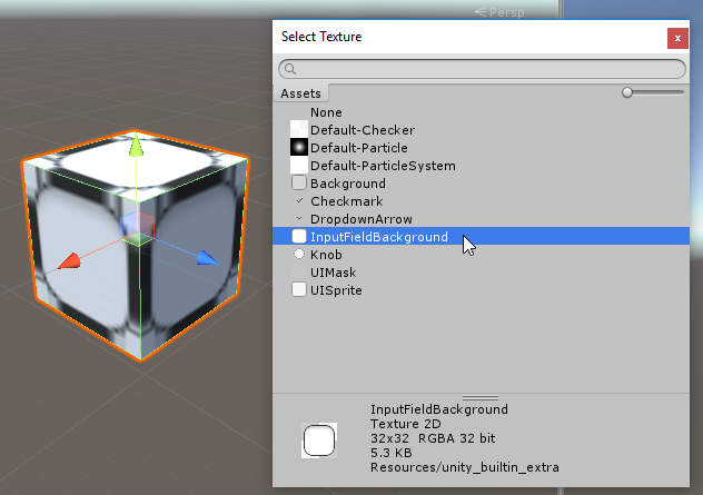
}The tex2D function is used to pick a colour for each pixel, from the texture, using the UV coordinates of the texture. This function is accessible within the CGPROGRAM block, as part of Nvidia’s C for Graphics library.
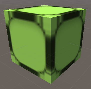
To see the result, just pick some random texture of whatever is included in Unity’s new project.
If you want to get really fancy, you can multiply or add the rgb values from the _myColour property, onto the texture you’ve selected. This would be done in the surface function, when setting the albedo:
void surf(Input IN, inout SurfaceOutput o) {
	o.Albedo = tex2D(_newTex, IN.uv_newTex).rgb * _myColour.rgb;
}
Multiplying colours together can have interesting effects. Since the RGB channels go from 0 to 255, it is essentially just number multiplication (so multiplying with black will result in black, because you are multiplying with zeroes).
That’s about it for the anatomy of regular surface shaders. As I mentioned, there are also other types which look a little differently, but starting with the surface shader anatomy lies a good foundation to explore those other types in future articles.
Next article I will look at lighting models and eventually introduce the different types of texture property maps (eg. normal maps, specular maps etc.). That’s when the real magic begins!